Digital Thermostats
Modbus FCU Thermostat Integration: 7 Checks Before BMS Commissioning
A Modbus FCU thermostat may work perfectly on its own but still have communication problems when connected to a Building Management System (BMS).
Sometimes the BMS cannot find the thermostat. In other cases, it can read the room temperature but cannot change the setpoint or fan speed.
These problems often come down to a few things: wiring, communication settings, register addresses, or control permissions.
If you are installing Modbus thermostats in a hotel, office, or commercial building, here are seven things worth checking before commissioning.
1. Confirm the Modbus Communication Type
First, make sure the thermostat and BMS can communicate using the same protocol.
Many FCU thermostats use Modbus RTU over RS485. This is different from Modbus TCP, which operates over an Ethernet network.
If the BMS uses Modbus TCP only, you may need an RTU-to-TCP gateway.
Before choosing a thermostat, check:
- ● Does the BMS support Modbus RTU?
- ● Is an RS485 communication port available?
- ● Will the thermostats connect directly to the BMS controller or through a gateway?
Confirming this early can save a lot of work later.
2. Check the RS485 Wiring
Poor RS485 wiring is a common reason for unstable communication.
In a typical Modbus RTU network, multiple thermostats share the same communication bus.
For reliable communication:
- ● Use suitable twisted-pair cable for RS485.
- ● Follow the recommended bus topology and avoid unnecessary long branches.
- ● Check the A/B or D0/D1 terminal definitions in the device manuals.
- ● Follow the equipment instructions for termination and biasing.
- ● Keep communication cables away from sources of electrical interference where possible.
One important point: RS485 terminal labels are not always consistent between manufacturers. Do not rely on the letters A and B alone. Check the wiring diagrams of both devices.
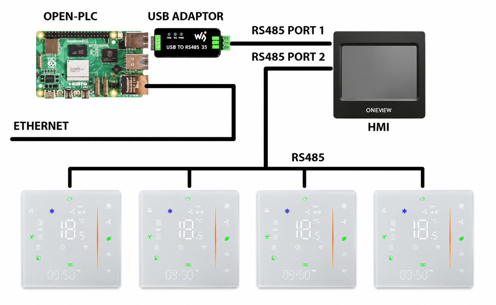
For larger projects, confirm the permitted cable length and number of devices with the BMS contractor.
For other installation issues, see our guide to common FCU thermostat wiring mistakes.
3. Set the Correct Device Address
Each Modbus thermostat on the same RTU bus needs a unique slave address.
For example, a hotel may have 30 rooms connected to one RS485 segment. Each thermostat needs its own address so the BMS can communicate with the correct room.
If two devices use the same address, communication problems may occur.
A simple address plan helps:
| Room | Thermostat address |
|---|---|
| 101 | 1 |
| 102 | 2 |
| 103 | 3 |
| 104 | 4 |
Example only. Actual addresses depend on the project.
We recommend preparing the address list before installation.
For larger buildings, keep a record of which thermostat belongs to each room, floor, and communication segment.
This makes commissioning and future maintenance easier.
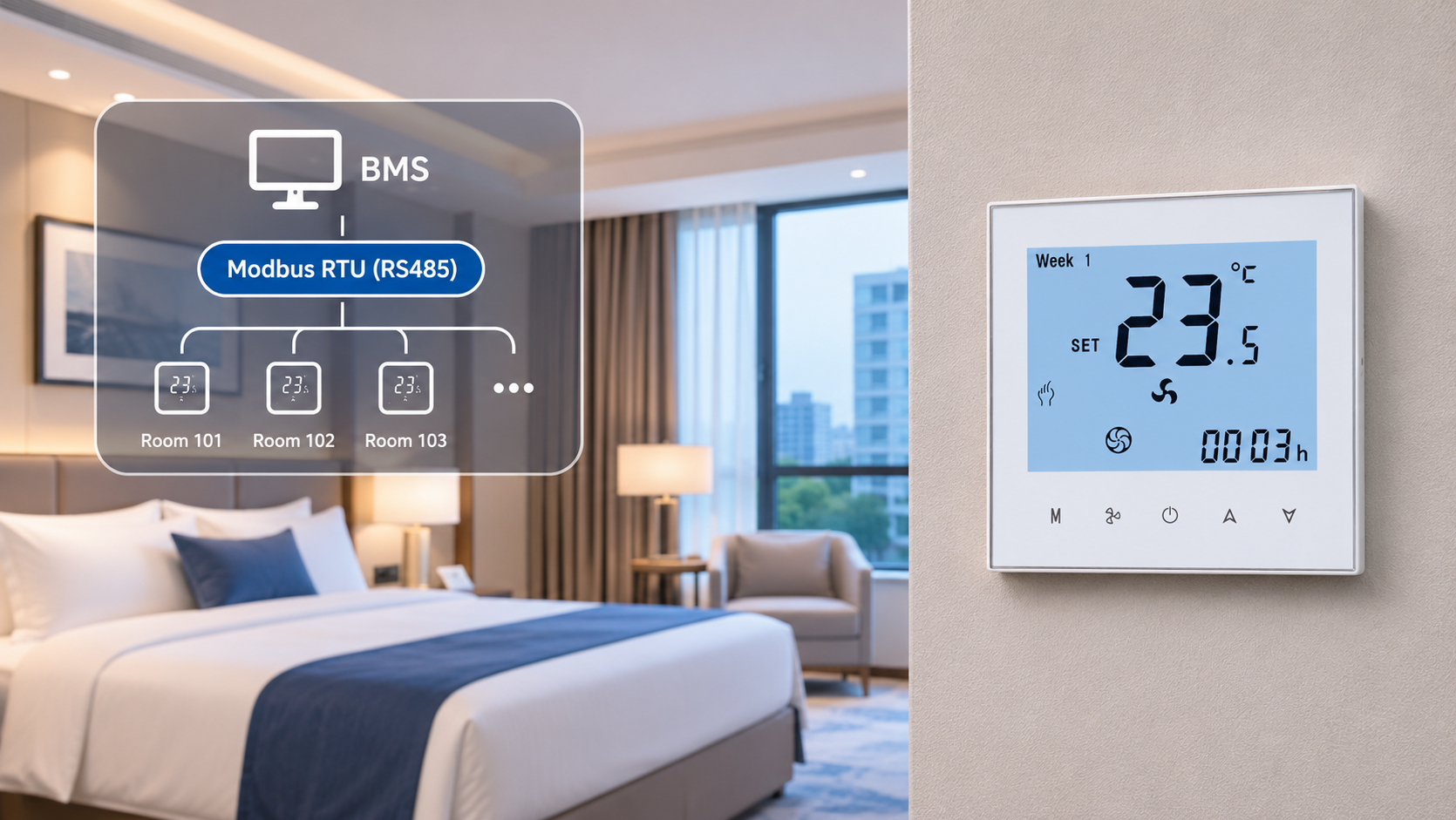
4. Match the Communication Settings
Even with correct wiring and addresses, the thermostat may not respond if its communication settings do not match the BMS.
Check these parameters:
- ● Baud rate
- ● Parity
- ● Data bits
- ● Stop bits
- ● Slave address
For example, if the BMS is configured for 9600 baud but the thermostat uses 19200 baud, they will not communicate correctly.
The settings available can differ between thermostat models.
Always check the technical manual for the exact model rather than assuming all Modbus thermostats use the same default settings.
5. Check the Modbus Register Map
This is one of the most important steps.
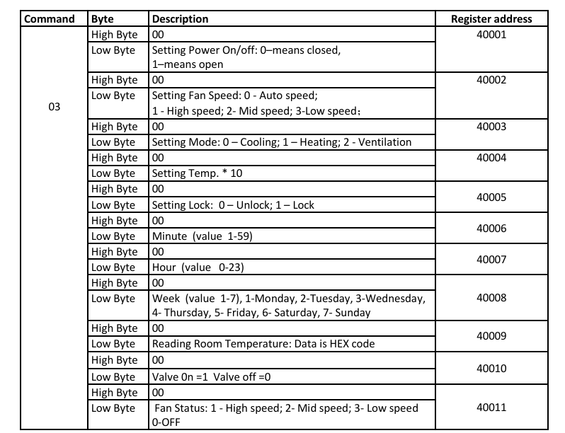
A Modbus register map tells the BMS which addresses to use for reading or writing thermostat data.
For an FCU thermostat, the required points may include:
| Data point | Typical purpose |
|---|---|
| Room temperature | Read the current room temperature |
| Setpoint | Read or change the target temperature |
| Operating mode | Monitor or select heating, cooling, or fan mode |
| Fan speed | Monitor or change fan operation |
| On/Off status | Monitor or control thermostat operation |
| Valve status | Monitor valve operation, if supported |
Not every thermostat supports all these functions through Modbus.
For example, one model may allow the BMS to read the fan speed but not change it. Another model may support both.
Also, check the register data format.
A value may use a scaling factor. For example, a raw value of 235 could represent 23.5°C if the register uses a scale of 0.1.
Some Modbus software also uses different address numbering conventions, so the displayed register number may not be the actual address sent in the request.
Before ordering thermostats for a BMS project, ask for the register map and confirm that all required data points are available.
This is especially important when replacing an existing BMS thermostat with a different brand.
6. Test the Actual FCU Control Logic
Successful Modbus communication does not automatically mean the FCU will operate as expected.
The thermostat must also match the fan coil system.
Check the actual configuration:
- ● Pipe system: 2-pipe or 4-pipe
- ● Fan control: 3-speed or 0–10V EC fan
- ● Valve control: ON/OFF or 0–10V modulating valve
- ● Operating modes: Heating, cooling, and auto mode where required
Then test how the thermostat responds to BMS commands.
For example, when the BMS changes the cooling setpoint from 24°C to 22°C, does the thermostat accept the new value?
If the BMS changes the operating mode, does the thermostat follow the command?
What happens when someone changes the setpoint locally?
These questions matter because BMS control and local thermostat control need clearly defined behavior.
Some projects require central control to have priority. Others allow occupants to adjust the room temperature within a limited range.
For automatic heating and cooling, confirm the changeover conditions and how the valve outputs respond.
If you are choosing between different valve types, our ON/OFF vs 0–10V valve control guide explains the differences.
If the project requires special control logic, discuss it with the thermostat supplier before ordering.
7. Run a Small BMS Test Before Bulk Installation
For a large hotel or commercial building, it is worth testing a few thermostats before installing hundreds of units.
A small bench test can reveal problems that are difficult to fix after installation.
We suggest testing the following:
| Test | What to confirm |
|---|---|
| Device detection | BMS can communicate with the thermostat |
| Temperature reading | Room temperature is displayed correctly |
| Setpoint writing | Thermostat accepts the BMS command |
| Mode control | Heating and cooling commands work as expected |
| Fan control | Fan speed changes correctly |
| Communication recovery | Device reconnects after communication is restored |
| Local operation | Thermostat behaves as specified when BMS communication is unavailable |
Do not stop after confirming that the BMS can read the room temperature.
Try actual control commands and check the response at the thermostat and FCU.
If the project uses a particular BMS controller or gateway, test with that equipment whenever possible.
Once the test is successful, record the thermostat model, firmware version, communication settings, and register map version.
These records will be useful during final commissioning.

What If the Modbus Thermostat Is Not Communicating?
If communication fails, start with the basics rather than changing several settings at once.
| Problem | What to check first |
|---|---|
| BMS cannot find any thermostat | RS485 wiring, communication port, baud rate, and network settings |
| Only one thermostat is offline | Device address, wiring connection, and power supply |
| Room temperature reads incorrectly | Register address, data format, and scaling |
| BMS can read but cannot change settings | Register write permissions and control settings |
| Communication is unstable | Bus topology, termination, cable length, and electrical interference |
If the problem remains, test one thermostat directly with a suitable Modbus master tool.
This can help identify whether the problem is related to the thermostat, the communication network, or the BMS configuration.
Choosing a Modbus FCU Thermostat for Your Project
When selecting a thermostat, don't look at Modbus support alone.
Two Modbus FCU thermostats may have very different fan outputs, valve controls, operating modes, and register functions.
At Beris Tech, we offer FCU thermostat options for different HVAC and BMS applications, including selected models with Modbus RS485 communication.
Before recommending a model, we normally need to understand:
- ● Your FCU system: 2-pipe or 4-pipe
- ● Your fan type: 3-speed or 0–10V EC fan
- ● Your valve type: ON/OFF or 0–10V
- ● Your BMS controller or gateway
- ● The data points you need to read or control
You can explore our FCU thermostat product range to see available models.
If you are still comparing different thermostat options, our Top 10 FCU Thermostats guide may also help.
Final Thoughts
Modbus FCU thermostat integration is not only about connecting two communication wires.
The thermostat, FCU, and BMS must work together.
Checking the wiring, communication settings, register map, and control logic before installation can help prevent delays during commissioning.
And for larger projects, testing a few samples before placing a bulk order is usually time well spent.
Working on an FCU project with Modbus integration?
Send Beris Tech your FCU configuration and BMS requirements. We can help you review suitable thermostat options and provide the relevant technical information for compatibility checking.
Contact: diane@beris-tech.com
Website: www.beris-tech.com
