Digital Thermostats
2-Wire vs 3-Wire Valve Actuators: How to Match an FCU Thermostat?
“Does your FCU thermostat work with a 3-wire valve?”
Before answering, we need to see the actuator’s wiring diagram. Some 3-wire actuators require separate opening and closing circuits. Others use a permanent power supply and a single control signal. They have the same number of wires, but the thermostat connections are different.
Whether you are replacing an existing fan coil thermostat or specifying controls for a new project, check the valve actuator requirements before choosing the thermostat. The display, communication protocol and fan speeds may all be suitable, while the valve output still needs a closer look.
What does a 2-wire valve actuator need?
A common arrangement in fan coil systems is a 2-wire On/Off valve actuator. The thermostat switches the specified supply to the actuator, which opens or closes according to its design.
For example, a normally closed, spring-return valve assembly opens when powered and returns closed when power is removed. Normally open versions operate differently, so the power-loss position should be checked in the actuator documentation.
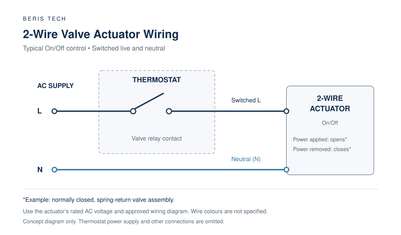
For a compatible FCU thermostat, confirm:
- The actuator’s rated supply voltage.
- Its operating and starting load.
- Whether the thermostat provides switched voltage or a volt-free contact.
- The required valve action when the output is on or off.
An “On/Off valve output” is a useful starting point, but it does not tell you everything about electrical compatibility.
3-wire valve actuators: two wiring arrangements to check
A 3-wire valve actuator may use two-control wiring or one-control wiring. These descriptions refer to how the actuator is powered and commanded.
The two arrangements below show why the wiring diagram matters when selecting a thermostat for a 3-wire valve.
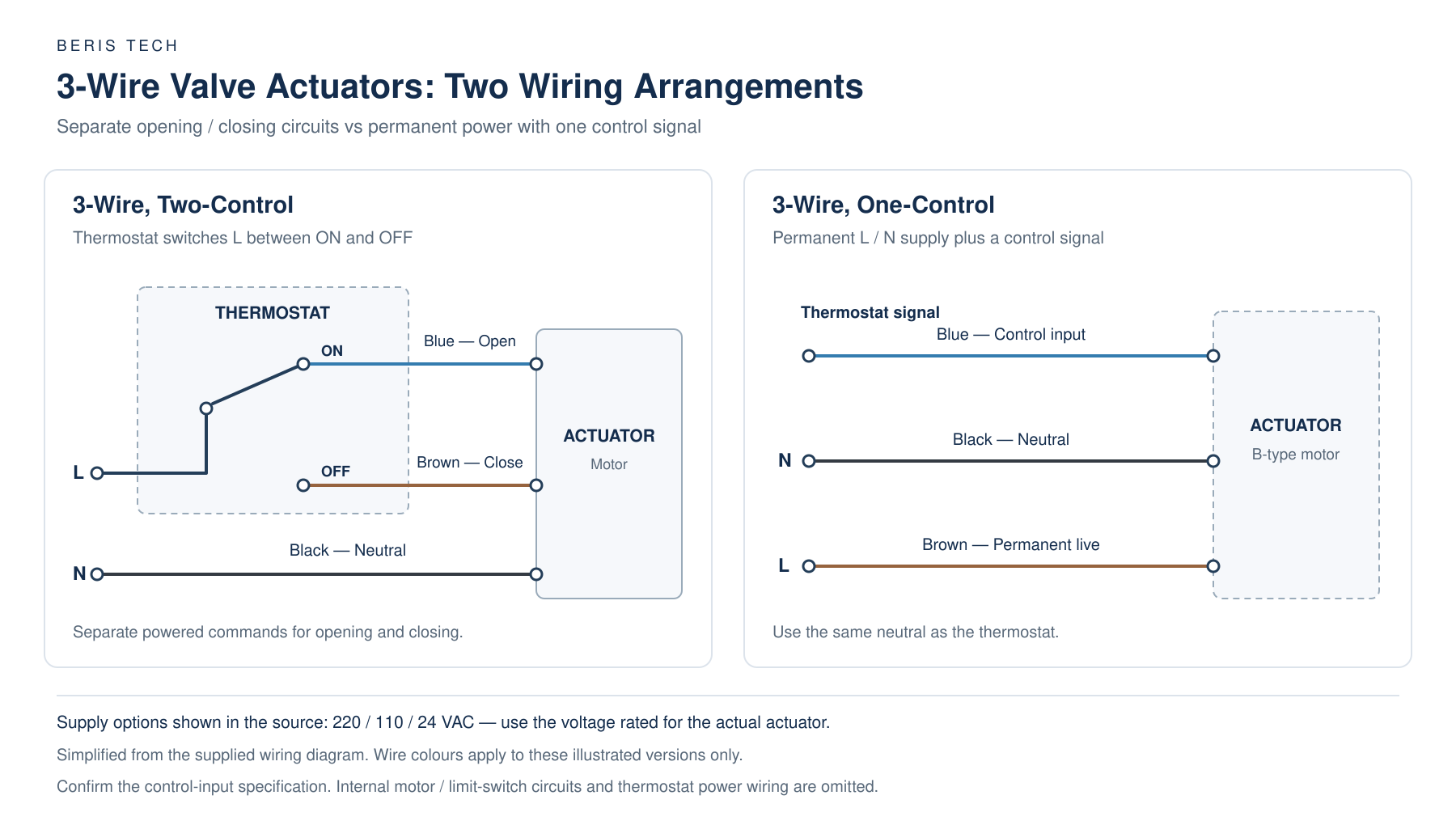
3-wire, two-control: separate opening and closing circuits
In the illustrated 3-wire, two-control arrangement, the connections are:
| Wire colour | Connection | Function |
|---|---|---|
| Black | N | Neutral |
| Blue | ON | Powered connection for opening the valve |
| Brown | OFF | Powered connection for closing the valve |
The thermostat switches the live supply between the blue and brown wires. When opening is required, it supplies the ON connection. When closing is required, it switches the supply to the OFF connection.
This means the actuator needs an electrical command for both directions. Simply removing power from the opening wire does not provide the closing command shown in this diagram.
The FCU thermostat therefore needs a suitable changeover output or an equivalent manufacturer-approved opening and closing output arrangement.
When reviewing a thermostat specification, check that these outputs are intended to control one valve. Separate outputs for heating and cooling valves are not automatically suitable as an opening and closing pair.
3-wire, one-control: permanent power plus one signal
In the illustrated 3-wire, one-control arrangement, the connections are:
| Wire colour | Connection | Function |
|---|---|---|
| Brown | L | Permanent live supply |
| Black | N | Neutral |
| Blue | Thermostat signal | Separate control input |
The brown and black wires provide the actuator’s power supply. The blue wire receives the control signal from the thermostat.
Unlike the two-control arrangement, the thermostat does not switch between separate opening and closing wires. The actuator uses its permanent supply and control input to perform the required operation.
The supplied wiring diagram specifies that the actuator neutral must be the same as the thermostat neutral. The electrical requirements of the blue control input must also match the thermostat output.
Before connecting it, confirm the required signal voltage, switching arrangement and the valve’s response when the signal is applied or removed. The diagram identifies the control wire, but it does not fully describe those signal requirements.

Which arrangement does your thermostat support?
For 3-wire, two-control wiring, check whether the thermostat can supply the opening and closing circuits correctly.
For 3-wire, one-control wiring, check whether its output matches the separate control input, while the actuator receives the specified permanent supply.
Wire colours in these examples apply to the illustrated actuators. Other models may use different colours or terminal labels. Likewise, the voltage options shown on the wiring diagram refer to the appropriate actuator versions; use the voltage stated on the actual unit.
FCU thermostat and valve actuator compatibility checklist
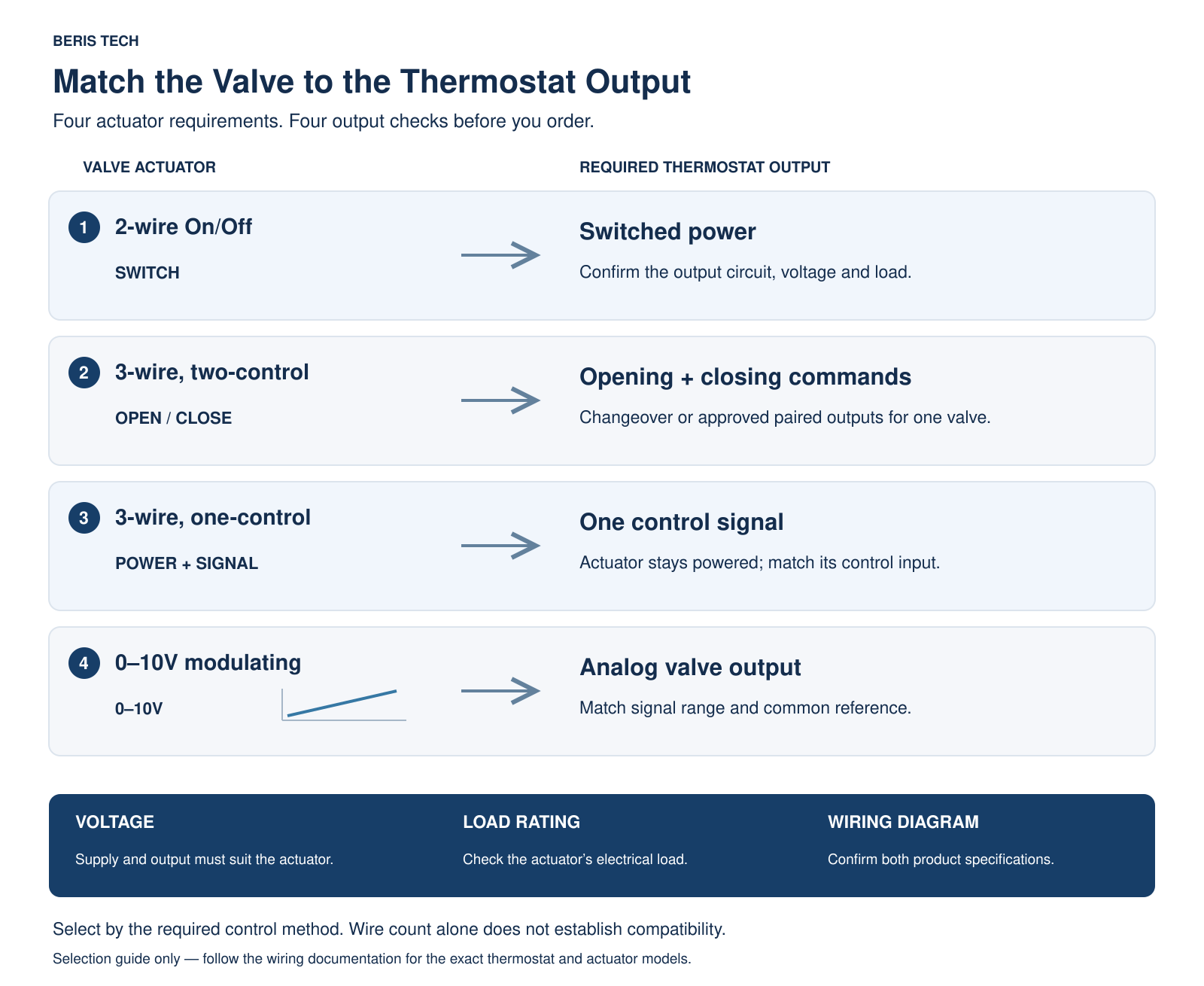
Before ordering a sample or approving a replacement, compare the actuator wiring diagram with the thermostat’s output specification.
| Actuator requirement | What to confirm on the thermostat |
|---|---|
| 2-wire On/Off | Suitable switching output, actuator voltage and load rating |
| 3-wire, two-control | Suitable changeover output or approved separate opening and closing outputs for one valve |
| 3-wire, one-control | Output matching the separate control input, with the actuator permanently powered as specified |
| 0–10V modulating | Compatible analog valve output, signal range and common-reference requirements |
A 0–10V modulating actuator is a separate selection case. Do not treat it as either of the illustrated On/Off arrangements just because a similar number of conductors is used.
For more detail on that choice, see our On/Off vs 0–10V valve control guide.
Three electrical checks are particularly useful during thermostat selection.
Check supply voltage and output voltage separately
A thermostat powered by 230VAC does not necessarily provide an output suitable for a 24VAC actuator.
Check how the valve output is supplied and what voltage appears at the relevant terminals. If the actuator needs a separate power supply, that requirement should be included in the project specification.
Identify switched voltage or a volt-free contact
A volt-free contact does not supply power. It switches a separately supplied circuit within its rated limits.
A switched-live output works differently. The distinction matters when matching both a 2-wire actuator and the control input of a 3-wire actuator.
Check the actuator load
Confirm the actuator’s running and starting requirements against the relevant thermostat output rating.
If one output will operate several actuators, have the combined load and connection arrangement reviewed before ordering. Matching the supply voltage alone does not establish that the output can carry the load.
Does BACnet or Modbus guarantee valve compatibility?
No. Communication and valve control are separate parts of the thermostat specification.
A BACnet FCU thermostat may communicate correctly with a building management system while having the wrong output arrangement for the installed valve. The same applies to a Modbus thermostat.
Instead of specifying only “BACnet thermostat for a 2-pipe FCU,” include the actuator model, rated voltage and wiring diagram.
The fan requirement should also be listed separately. For example, a 0–10V fan output should not be assumed to be available for controlling a modulating valve.
Providing these details together helps the supplier assess the complete configuration before recommending a model.
Explore Beris Tech FCU thermostats for your project. Check each model’s fan control, valve output and communication options to find a suitable configuration.

What to send before requesting a quotation
For an FCU thermostat quotation, the actuator label and wiring diagram are a useful starting point. They help identify requirements that may be missing from a short project description.
To help us assess a Beris Tech thermostat for your application, send:
- Actuator details: brand, complete model number, label photograph and wiring diagram.
- Power supply: the voltage available at the thermostat and the actuator’s rated voltage.
- FCU configuration: 2-pipe or 4-pipe.
- Fan control: 3-speed or 0–10V.
- Communication: any WiFi, Modbus or BACnet requirement.
- Project details: quantity and expected installation schedule.

For a replacement project, include the existing thermostat model and terminal diagram as well. If the documentation is missing, ask the installer to identify the existing connections before selecting a replacement.
We can review this information and advise whether an available Beris Tech configuration meets the requirement. Compatibility should be confirmed for the exact thermostat and actuator models before ordering.
Need help matching an FCU thermostat to your valve actuator?
Email the actuator label and wiring diagram to diane@beris-tech.com, together with your project requirements.